The fuse board (D60, task B5)
One JLCPCB board that takes the place of the eleven inline MINI holders and the Blue Sea shunt on the power plate in
P3: twelve MINI 58V fuse holders, the 1 mOhm shunt and the INA228 that reads it, the - star point and the frame bond.
Everything here is generated: hardware/fuse-board/design.py (parts, nets, placement), generate.py (the KiCad 10
schematic and PCB), build.sh (checks, fabrication files, pictures), analysis.py (the numbers below), and
cad/body_fuse_board.py (the board as the body sees it). Written 2026-10-27; prices read that day. Revised the same day for D65 (two DeWalt DCB609 packs in series: a 10S bus,
30-41 V, no charge port) and D66 (the turret on its own fused branch of the bus; one TRACO TEP 150-4812WI, 12 V
12.5 A isolated, feeds the J501 and the 12 V rail in place of both DDR converters).
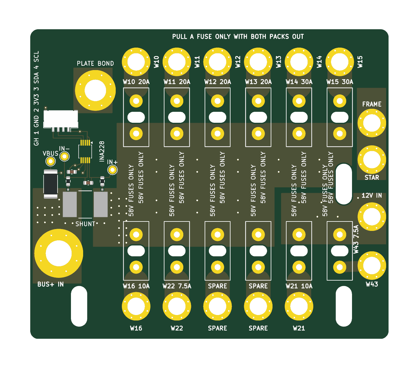
| Board | 88 x 76 mm, 2 layers, 2 oz (70 um) copper, 1.6 mm FR-4, lead-free HASL, green |
| Where | robot x 34..122, y -14..62 on the power plate's top face (z 138.2); the board at z 148.2..149.8 on 10 mm printed standoffs; fuse tops at z 174.2 |
| Holders | 12 x Littelfuse MINI FL1 178.6764.0001 (58 V DC, 22 A continuous, fuses to 30 A): ten on the + bus (two of them spares), two on the 12 V rail |
| Shunt | Bourns CSS2H-3920R-1L00F, 1 mOhm 1 %, 8 W, on the high side between the MRBF and the + bus |
| Monitor | INA228 (U1, TSSOP-10) on the board, or the Adafruit 5832 wired to three pads (TP1-TP3); I2C on a JST GH 4-pin |
| Studs | M6 for the 80 A input; M4 for every branch, the 12 V input, the star point and the frame bond |
| Checks | KiCad DRC clean against JLCPCB's 2 oz rules, schematic parity 0, ERC 0 (hardware/fuse-board/reports/) |
| Price | JLCPCB $40.60 for 5 boards (instant price from the uploaded zip); one board built for $154.48 in parts and packs |
| Mass | 132 g with its screws, nuts and standoffs (45 g the bare board with its holders) |
1. What changed from the brief, and why
The shunt is on the + side, not in the pack's - lead. The brief put the 1 mOhm shunt where the Blue Sea shunt is today (W5, W6, W9: between the XT90's - and the main switch's IN-). The INA228's inputs may not go more than 0.3 V below its own ground (TI SLYS021A, absolute maximum, both pins). Its ground is the MCU's, the switched - bus. With the shunt in the pack's - lead before the low-side switch, turning the switch off lets the - bus float up toward the + bus (the loads pull it there) while the INA228's inputs stay at the pack's -: its input clamps then carry the robot's load current round the open switch, which destroys the INA228 and leaves the switch bypassed through a 22 AWG sense lead. On the + side the INA228's inputs sit 0 to 41 V above its ground whether the switch is on or off, which is the INA228's own high-side application (TI's figure 8-2). (Under D65 the packs charge on DeWalt's chargers, off the robot; the regeneration that flows back into them reads with the opposite sign.) The low-side fix, an isolated INA228 (I2C isolator and a 1 W isolated supply), was the alternative: more parts for the same result.
This applies to P0 as wired today: the Adafruit INA228 across the Blue Sea shunt in the - lead, grounded on the MCU, sees exactly this when the switch goes off. Before bring-up step 4 either move the Blue Sea shunt into the + lead (MRBF load stud to the + bus bar's tap 1), or leave the INA228's VIN+/VIN- unconnected until the board arrives.
Littelfuse MINI FL1 holders, not Keystone 3568. Keystone rates the 3568 at 20 A at 500 V AC with no DC rating (Keystone catalogs M55, 2006, and M60, 2013, page 40; TME lists 20 A; some distributors list 30 A without a source; Keystone's own drawing, rev C 2019, states none), so it does not carry the VESC branches' 30 A fuses. The 3570 is not a MINI holder (a 6.3 x 32 mm fuse clip; LCSC lists no specification). The Littelfuse MINI FL1 (178.6764.0001) is rated 58 V DC, 22 A continuous, for MINI fuses up to 30 A (Littelfuse's product page, read 2026-10-27; its 2016 datasheet says 125 V, LCSC's text 32 V). It is the only PCB MINI holder found with a DC rating at the bus voltage, so D55's "32 V holder on the battery bus" ends with it; the "58 V FUSES ONLY" silk stays at every holder because a standard 32 V MINI fuse may still fit it (check on arrival whether one seats). The holder's 22 A continuous sets a rule for the wheels: the VESCs' battery current limit at 20 A (VESC Tool, "Battery Current Max"; the motor current limit can stay higher, the battery current at low speed is a fraction of it). The 30 A fuses stay (the fuse's own derating puts its continuous load at 22-24 A at 40-60 C).
The turret's feed (D66): 7.5 A, not 10 A, through the stop relay's pole B. The turret takes about 40 W and bursts to about 140 W: 4.7 A at 30 V, 3.4 A at 41 V. The stop relay is the Omron G2RL-2 (DPDT): rated 8 A at 30 V DC resistive and 8 A carry at 70 C (5 A at 85 C). Its maximum switching capacity curve for the 2-pole type (Omron's datasheet, engineering data) holds 8 A to about 39 V and falls steeply above: read off the curve, about 6 A at 41 V and about 1 A at 55 V, for resistive loads. The turret's 3.4 A at 41 V is inside it, with no margin to spare, and Omron gives no DC endurance above 30 V. A 10 A fuse would let the contact carry past its 8 A rating in an overload; the 7.5 A MINI 58V keeps it under (Littelfuse derates a 7.5 A fuse to 6.0 A at 40 C: the 4.7 A burst is inside that). The relay opens with the turret's safety loop (pole A) at the same instant, which stops the flywheels, so the current it breaks is mostly the reComputer's idle draw. Two things to measure at the P2 bring-up (B12/B15): the inrush when the relay closes onto the turret's input capacitance (the 7.5 A fuse's I2t is 68 A2s; if it blows or the contact pits, the turret needs its own soft start, or pole B's job goes to a DC-rated relay or a high-side MOSFET driven from the coil line), and the contact after a hundred stops.
88 x 76, not 120 x 42. A holder and its stud need about 27 mm in line (the 14.2 mm holder, its output run, a 7 mm stud and the lug's edge) and 10 mm across (the M4 lugs side by side). Twelve in one row is 120 mm long and 27 mm deep, which leaves 15 mm of the 42 for the + bus feeding them and nothing for the M6 input, the shunt, the INA228, the 12 V input or the star and frame studs; two rows back to back with the bus between them need about 66 mm of depth. The board takes the whole free area of the plate (x 34..122, y -14..62). It sits 36 mm tall over the plate (10 mm standoffs, the holder and the fuse), 6 mm more than the brief's 30: the deck's underside is at z 213.5, 39 mm above the fuses.
2. The schematic in words
hardware/fuse-board/pictures/schematic.pdf; the nets are global labels named as below.
- +BAT_IN: J1, the M6 stud the MRBF's load stud feeds (W4, 8 AWG), poured on both layers to the shunt's pad 1.
- R1, the shunt: pad 1 +BAT_IN, pad 4 +BUS. Its Kelvin taps (pads 2 and 3, net-tied to 1 and 4 inside the footprint) sit at Bourns' measurement points, 8.40 mm apart, and leave sideways of the current.
- +BUS: a band poured on both layers between the two rows of holders, stitched with 36 vias; it feeds F1-F10.
- +12V: J14 (W40, 14 AWG, from the TRACO TEP 150-4812WI's +V, up to 12.5 A) to F11 and F12, its own pour.
- F1-F12: each holder's pin 2 runs to its own M4 stud (J2-J13): OUT_W10 ... OUT_W43, OUT_SPARE9, OUT_SPARE10. On the + bus: F1-F4 the RS-04s (20 A), F5-F6 the VESCs (30 A), F7 the TRACO's input (W16, 10 A), F8 the turret (W22 to the stop relay's pole B, 7.5 A), F9-F10 spares. On the 12 V rail: F11 the J501 (W21, 10 A), F12 the rest of the rail (W43: lidar box, SSC1 lights, eyes, the 5 V buck; 7.5 A).
- The INA228: R2 and R3 (10 Ohm, TI's protection against a hard short's dV/dt) from the taps to IN- and IN+; C1 (100 nF, 100 V) across them; VBUS through R4 (4.7 kOhm, 1 W 2512: 11 mA if VBUS ever shorts) from +BAT_IN; VS on 3V3 with C2; A0 and A1 to ground (address 0x40); ALERT not connected (the firmware polls). IN+ is the bus side: positive current flows into the packs (regeneration); discharge reads negative.
- J17 (JST GH 4, SM04B-GHS-TB): 1 GND, 2 3V3, 3 SDA, 4 SCL, to the MCU carrier (W42); the I2C pull-ups (4.7 kOhm) are on the carrier. The order is the board's, chosen so the four lines leave the INA228 without crossing; the body makes this lead.
- The Adafruit 5832 instead of U1 (U1 is not fitted while LCSC has none): its 15 mOhm shunt removed and its VBUS jumper open, VIN+ to TP2, VIN- to TP1, VBUS to TP3, its STEMMA QT lead to the MCU, mounted on the MCU carrier as in P0. Not both: both answer at 0x40. TP1-TP3 are also the meter's Kelvin points for the calibration.
- BUS- (the switched - bus): J15, the star stud (W23, the TRACO's -V tie, and W41 from the - bus bar), J16, the frame-bond stud (W33 on its own stud, so the bond is never loosened with the star), MH1 (the plate bond), U1's ground and J17's ground, joined by a strip on the bottom along the north edge.
3. Layout and mounting
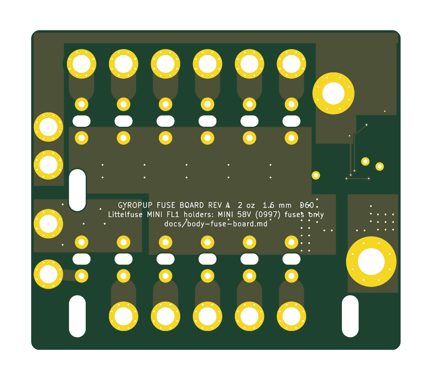
The holders stand in two rows of six across the robot, 10 mm apart, inputs toward the + bus band between the rows, outputs outward to a row of studs on each long edge: the four RS-04s and the two VESCs along the board's left edge (+y, toward the MCU board), the TRACO's input, the turret, two spares and the J501 along its right edge (-y, toward the bus bars), the 12 V rail's branch, the 12 V input and the star and frame studs at its front (+x, beside the MRBF block). The power entry (J1, the shunt) and the INA228 are in the strip at its rear (-x); MH1 sits on the plate's old shunt nut.
Mounting (all into features the P1 plate already has):
- MH1, robot (50, 47): an M5 x 14 socket head (91290A230) down through the plated hole and a printed standoff (OD 12, 10 mm) into the plate's flush nut (the Blue Sea shunt's base nut). It bonds the plate to the - bus: the plate stands on printed posts and was otherwise floating under every + lead of the skid (hazard 10).
- Three cable ties (7130K12) through the plate's old fuse-bundle slots at (46, -6), (111, -6) and (111, 24), a
printed tie block (10 mm, a 4 x 10 slot through it) and the board's own 4 x 10 slots, round the block. The body's
commit 40c427b shrank
plate_fusesto 36 mm, which moves the plate's upper slots to y 18; at (111, 18) a slot would fall under F12's holder. Keep the plate's slot at (111, 24) (cad/body_fuse_board.MOUNTShas it), or the board is held by MH1, the two lower ties and its sixteen stud feet only. - Every stud is its own standoff: a printed foot (OD 12 for M4, 16 for M6, 10 mm) under the stud with a hex pocket at its top holding the nyloc (M4: 7.2 AF x 5.3; M6: 10.2 AF x 6.3) and the screw's hole through it. The lug sits on the top pad and the screw goes down through the lug and the board into the nut: copper to copper, serviced from above, as the bus bars' insulators hold their nuts. M4 x 12 (91290A148) at every M4 stud (with one 18 AWG ring the tip stops 0.4 mm short of the plate, with the star's three rings 2.0 mm), M6 x 12 (91290A318) at J1.
- Print them in PETG (PA6-GF if the plate runs over 60 C), never a carbon-filled filament: the standoffs hold nuts at different potentials. Bambu publishes no resistivity for PA6-CF and chopped carbon fibre in nylon ranges from dissipative to conductive; the same question stands for the bus bars' PA6-CF insulators (section 10).
- Under the board stay clear of the two VESC flange screws whose tips stand 4.5 mm above the plate at (41, 29.15) and (41, 56.15): no stud is over them.
The layout item for cad/body_layout.py is body_fuse_board.LAYOUT_ITEM (name plate_fuse_board, which is what
lever_taken('fuse_board') looks for): it replaces plate_fuses and plate_shunt; the board's mass and box come from
cad/body_fuse_board.py.
4. The copper
IPC-2221B's external-conductor curve, per layer, with each conductor's current split equally between the two layers (they meet at every holder pin and at every stud's ring of vias). Its charts stop at 35 A and 10.2 mm; beyond them it is extrapolated and marked so. Fault let-through against the copper: IEC 60949's adiabatic K for copper from 60 to 200 C against the fuse's typical pre-arcing I^2t (Littelfuse 0997 datasheet).
| Holder | Branch | Fuse | Copper (each layer) | IPC-2221 width needed for +20 C | Rise at the fuse's rating | Neck past the peg (2.6 x 3.6 mm) | Fault I^2t margin |
|---|---|---|---|---|---|---|---|
| F1-F4 | RS-04 x 4 (W10-W13) | 20 A | 6.0 mm | 2.4 mm | 4.3 C | +0.2 C | 6.9 |
| F5, F6 | VESC L, R (W14, W15) | 30 A | 6.0 mm | 4.1 mm | 10.8 C | +0.5 C | 2.4 |
| F7 | TRACO TEP 150-4812WI in (W16) | 10 A | 6.0 mm | 0.9 mm | 0.9 C | 0 | 28 |
| F8 | the turret, via the stop relay (W22) | 7.5 A | 6.0 mm | 0.6 mm | 0.5 C | 0 | 39 |
| F9, F10 | spares (sized for 30 A) | - | 6.0 mm | 4.1 mm | 10.8 C | +0.5 C | 2.4 |
| F11 | J501 at 12 V (W21) | 10 A | 6.0 mm | 0.9 mm | 0.9 C | 0 | 28 |
| F12 | the 12 V rail (W43) | 7.5 A | 2.6 mm | 0.6 mm | 1.8 C | 0 | 39 |
The 12 V pour (12.6 mm on both layers, six vias) carries the TRACO's full 12.5 A from J14 at +0.4 C; J14 is an M4 stud with a 16-14 AWG ring on W40 (14 AWG).
Every branch carries its fuse's rating at a few degrees; the heat at a holder is the fuse's own (2.6 W in a 30 A MINI at its rating, 1.9 W in a 20 A), which is why the holders are 10 mm apart. The neck is where the 6 mm run passes the holder's peg slot; it is 3.6 mm long between two large copper ends and rises half a degree.
The main path (J1, the shunt, the + bus band):
| Section | Copper | At 40 A | At 80 A (extrapolated) | The 80 A, 0.3 s jump pulse |
|---|---|---|---|---|
| +BAT_IN pour, J1 to the shunt | 12 mm, both layers, 14 vias at the shunt | +6.6 C | +32 C | +3.4 C |
| + bus band beside the shunt | 14.4 mm, both layers, 20 vias at the shunt | +4.9 C | +24 C | +2.4 C |
| + bus band toward the holders | 30 mm, both layers, 16 vias | +1.5 C | +7 C | +0.5 C |
The shunt's pads are on the top only, so the bottom layer's half comes up through the vias beside them: 1.4 A a via at 40 A, 2.9 A for the 0.3 s pulse. The board's continuous rating is 40 A, set by the shunt, not the copper: its 8 W rating needs its terminals under 70 C, and with about 21 C/W from its pads into the pours it reaches about 34 C over the board at 40 A (1.6 W) and would reach about 130 C at 80 A continuous (6.4 W). The jump's 80 A for 0.3 s is 1.9 J (the shunt's short-time rating is 5 x 8 W for 5 s), and the board takes 80 A for up to about 30 s. The duty the plan gives (80 A pulses, a few amps on average) is far inside this; the INA228's alert or the firmware can watch the RMS if a stalled motor ever holds the bus near 40 A.
Clearances (fuse-board.kicad_dru): 1.0 mm between every pair of different power nets and between power and
logic (IPC-2221B 51-100 V: 0.6 mm uncoated external, B2); 0.2 mm inside the shunt group (+BAT_IN, +BUS and the sense
lines differ by at most the shunt's 80 mV); 0.25 mm where the sense lines escape the INA228's 0.5 mm pins beside its
ground and logic (TI's own package puts VBUS 0.2 mm from GND; IPC-2221B B4, coated: 0.13 mm); the INA228's pin pitch
itself exempt. Copper is at least 0.3 mm from every edge and NPTH.
5. The INA228's accuracy
The error budget in % of reading (analysis.py); the board between 15 and 55 C, calibrated at 25 C.
| Source | Value | Removed by the calibration |
|---|---|---|
| Shunt tolerance | 1.0 % | yes |
| Kelvin taps at Bourns' measurement points (pad copper, solder) | 0.5 % (allowance) | yes |
| INA228 gain error (max) | 0.05 % | yes |
| 10 Ohm input resistors against the 92 kOhm input | 0.022 % | yes |
| Shunt TCR, 100 ppm/C with its copper terminals, over 30 C | 0.30 % | no |
| Shunt self-heating (12.5 C/W to its terminals; the 80 A pulse adiabatic) | 0.02-0.20 % | no |
| INA228 gain drift, 20 ppm/C over 30 C | 0.06 % | no |
| Offset 1 uV + drift 0.3 uV + CMRR 154 dB at 41 V 0.1 uV + thermal EMF 3 uV | 5.4 uV (0.27 % at 2 A) | no |
| The calibrating meter (10 A range) | 0.3 % | - |
| Current | Uncalibrated, worst case | Uncalibrated, RSS | Calibrated, worst case | Calibrated, RSS |
|---|---|---|---|---|
| 1 A | 2.47 % | 1.28 % | 1.20 % | 0.69 % |
| 2 A | 2.20 % | 1.19 % | 0.93 % | 0.51 % |
| 5 A | 2.04 % | 1.17 % | 0.77 % | 0.44 % |
| 10 A | 2.00 % | 1.16 % | 0.73 % | 0.43 % |
| 40 A | 2.15 % | 1.18 % | 0.87 % | 0.47 % |
| 80 A (0.3 s) | 2.13 % | 1.18 % | 0.85 % | 0.47 % |
Result: within 1 % of reading from 2 A to 80 A after a one-point calibration; not within 1 % without it (the shunt's own 1 % and the layout allowance are most of the error). Below 2 A the floor is about 5 mA plus 0.7 % of reading. The calibration (bring-up step 5, which already compares the INA228 with a meter): 5-10 A from a bench supply through the shunt (or a dummy load on the 12 V rail), read on a meter with 0.3 % or better on its 10 A range; set the firmware's scale (or SHUNT_CAL) so the INA228 agrees; record the factor in the build log. VBUS the same against the meter's DC volts (its 4.7 kOhm in series with the 1 MOhm VBUS input reads 0.47 % low before calibration). The INA228's SHUNT_TEMPCO can take the shunt's 100 ppm/C against the die temperature: the two sit 10 mm apart on the same copper.
6. JLCPCB
- Rules (
fuse-board.kicad_pro,fuse-board.kicad_dru), from jlcpcb.com/capabilities/pcb-capabilities read 2026-10-27: 2 oz, 2 layers: track and space 0.16 mm (we use 0.2 minimum), PTH annular ring 0.254 mm (vias 0.3/0.85 and 0.4/0.95, rings 0.275 mm), pad hole-to-hole 0.45 mm, copper to edge 0.2 mm (we use 0.3), NPTH slot width 1.0 mm (ours 2.7 and 4.0), legend line 0.15 mm and text 1.0 mm. - Checks:
build.shruns KiCad's DRC with zone refill and schematic parity and fails on any violation: 0 violations, 0 unconnected, 0 parity issues; ERC 0. The upload to JLCPCB parsed it as "2 layer board of 76x88mm" and priced it; JLCPCB's own engineering review of the files happens after an order is placed (not run: it needs an order). - Files:
fab/fuse-board-gerbers.zip(copper, mask, paste, silk, outline, PTH and NPTH drills with the oval slots as G85);fab/bom-jlcpcb.csvandfab/cpl-jlcpcb.csvfor the seven SMD parts if JLCPCB assembles them (check the shunt's, the 2512's and the GH's rotation in JLCPCB's placement preview). - Instant price, read with
jlcpcb_quote.pyfrom the uploaded zip (no account): $40.60 for 5 boards (2 oz outer copper $35.30 of it, lead-free HASL $1.30), $38.60 from JLCPCB's desktop app; DHL estimate $31.49; 3 days. Choose: 2 layers, 1.6 mm, 5 pieces, green, lead-free HASL, 2 oz outer copper, everything else default. - Assembly is optional: about $31 for two boards by JLCPCB's published Economic PCBA fees ($8.18 setup, $1.53 stencil, $3.07 for each extended part) plus the parts; an estimate, since its BOM step asks for a sign-in. The default below is hand assembly: the shunt on its 2 oz pours wants a hot plate or hot air with preheat, the rest is 0603 and a 1.25 mm GH.
7. Parts and prices
One board built from a 5-board PCB order (cad/body_fuse_board.py ORDER, the catalogue's entries):
| Part | Catalogue key | Qty | Seller (backup) | Paid |
|---|---|---|---|---|
| PCB, 5 boards | fuse_board_pcb | 1 order | JLCPCB (PCBWay) | $40.60 |
| Littelfuse MINI FL1 holder | fuse_holder_mini_pcb | 14 (2 spare) | LCSC C142933 $1.67 (TME $4.56) | $23.38 |
| Bourns CSS2H-3920R-1L00F shunt | shunt_1mohm_3920 | 2 | LCSC C4087295 $0.78 (C1848566 $1.50) | $1.57 |
| 10 Ohm 0603, 100 nF 100 V and 50 V 0603, 4.7 kOhm 2512 | res_10r_0603, cap_100n_100v_0603, cap_100n_50v_0603, res_4k7_2512 | LCSC minimums | LCSC (alternates listed) | $1.95 |
| JST GH 4 header, housings, 4 pre-crimped wires | gh_header_4p_smd, gh_housing_4p, gh_lead_2p_300 | 5, 2, 4 | LCSC, TLC Electronics | $6.97 |
| Ancor #8 heat-shrink rings 12-10, 16-14, 22-18 AWG | ring_12awg_m4, ring_14awg_m4, ring_18awg_m4 | 3, 12, 3 | go2marine 3-packs (25-packs) | $24.70 |
| M4 x 12 socket head, M4 nyloc, M6 x 12, M5 x 14, 4 in ties | screw_m4x12_socket, nut_m4_nyloc, screw_m6x12_socket, screw_m5x14_socket, cable_tie_4in | 100-packs | McMaster-Carr (next length up) | $53.59 |
| MINI 58V 7.5 A fuses (Littelfuse 099707.5WXN) | fuse_mini58_7a5 | 3 | LCSC C2680610 $0.58 (LCSC other suppliers $0.31) | $1.73 |
| Total | $154.48 before shipping |
Reused from P0: the eight MINI 58V fuses of 20, 30 and 10 A, the Adafruit 5832, W4's 8 AWG M6 lug and the bus bars' M6 nylocs. The standoffs are printed (about 26 g of PETG). The bare INA228 (ina228_ic, LCSC C2887910 $6.42, none in stock on 2026-10-27) is optional.
8. The P3 wire list
cad/body_fuse_board.P3_WIRES holds the rows in cad/body_wiring.py's form for the body to merge:
- W4 MRBF load stud to the board's J1 (was: the + bus bar's tap 1). The + bus bar carries nothing in P3: anything left on it would bypass the shunt.
- W5 the packs' - straight to the switch's IN-; W6 goes. W8, W9 go (D65: no charge port).
- W10-W15 from their M4 studs (J2-J7) with #8 rings (was: + bus taps through inline holders).
- W16 J8 (F7, 10 A) to the TRACO TEP 150-4812WI's Vin+ (18 AWG): 150 W out is about 5.6 A in at 30 V.
- W22 J9 (F8, 7.5 A) to the stop relay's pole B, then W34 from pole B to the turret's XT30 (16 AWG; D66): the radio stop still cuts the turret's power.
- W40 the TRACO's +V to J14 (14 AWG, 12.5 A); W21 J12 (F11, 10 A) to the J501's DC-IN at 12 V (16 AWG, XT30U-F); W43 (new) J13 (F12, 7.5 A) to the rest of the 12 V rail (16 AWG): the lidar box, the SSC1 lights, the eyes, the 5 V buck, about 40 W. W17, W24-W27 go with the DDR-60L-12.
- W23 the TRACO's -V tie to J15 (the star); W33 to J16 in 14 AWG (was 18): a + lead chafed through before its branch fuse puts the MRBF's let-through on the bond.
- New: W41 - bus bar tap 5 to J15 (14 AWG); W42 J17 to the MCU carrier (GH 4, 28 AWG pre-crimped: 1 GND, 2 3V3, 3 SDA, 4 SCL; 4.7 kOhm pull-ups on the carrier).
- W30, W31, W32 go (the sense pair and VBUS are on the board), unless the Adafruit replaces U1: then three short leads TP1, TP2, TP3 to its VIN-, VIN+, VBUS.
9. Building and testing it
- Order the PCB (section 6) and the parts (section 7); print 16 stud standoffs (15 x OD 12, 1 x OD 16), MH1's standoff and three tie blocks, 10 mm tall, in PETG.
- SMD first: the shunt (R1) with the board on a hot plate at about 150 C and hot air, then R2-R4, C1, C2, J17, and U1 if fitted. Inspect the shunt's four joints; R1's taps are the small pads outside its north edge.
- Holders: snap each FL1's peg into its oval slot (the slot takes the peg on either side of the terminals' line), check it sits flat, solder both terminals (a large tip: the + bus band is 2 oz on both layers).
- Insulation, before anything is bolted: more than 1 MOhm between +BAT_IN, +BUS, +12V, BUS- and every OUT_ stud, with no fuses in; +BAT_IN to +BUS reads about 1 mOhm (four-wire: 5 A in at J1, out at an output, mV across TP1-TP2).
- On the plate: the standoffs with their nylocs pressed in, MH1's screw into the plate's nut (plate to J16 under 0.1 Ohm), the three ties; then the lugs, each screw down through its lug into its standoff's nut.
- Bring-up (docs/body-electrical.md 6) with these changes: step 4's rails with the TRACO's fuses (F7, F11, F12) only; step 5 the calibration of section 5 against a meter; step 6 the RS-04 and VESC fuses one at a time. A fuse is pulled only with both packs out.
10. Still open
Arrival checks (before the board is built):
- The FL1 holder's DC voltage rating: Littelfuse's page says 58 V DC, its 2016 datasheet 125 V, LCSC's text 32 V. The board relies on the page (the bus is 41 V under D65, under every one of them but the last), and D55's rule (a fuse is pulled only with the packs out) stands regardless. Ask Littelfuse or read the label on the carton.
- Whether a standard 32 V MINI fuse seats in the FL1 (Littelfuse markets a rejection feature for its MINI 58V fuses). If it seats, the "58V FUSES ONLY" silk is the only guard, as with the inline holders.
- The FL1's peg side (section 9 step 3).
Open:
- P0's INA228 across the - lead shunt (section 1): fix before bring-up step 4.
- The turret's feed through the G2RL-2 at 41 V DC (section 1): the inrush and the contact at B12/B15.
- The plate's third tie slot at (111, 24), not (111, 18) (section 3).
- The VESCs' battery current limit at 20 A (the holder's 22 A continuous): for the firmware (B8) and the VESC Tool setup in B12.
- PA6-CF as an insulator: the bus bars' insulators (
cad/body_frame.py bus_insulator()) hold the + and - bars over the aluminium plate, which this board now bonds to the - bus. Bambu publishes no resistivity for PA6-CF; carbon-filled nylon can conduct. Measure a printed insulator (more than 100 MOhm at 50 V across it) or print them in PA6-GF or PETG. - JLCPCB's assembly price and its engineering review need a sign-in and an order; the PCB price is read.
- The mass: the board and its hardware are 131 g against the 195 g of inline holders, leads and Blue Sea shunt they replace: about -63 g, not the plan's -110 g (levers 7 and 8); most of the difference is steel (15 M4 screws and nuts, 42 g). Aluminium screws would bring back about 20 g.
- The height: 36 mm over the plate against the brief's 30; nothing above it until the deck.