Turret wiring and harness (v0, the bench build)
The electrics of the foam-ball turret as built for the bench (docs/decisions.yaml D42): every connector and its pinout,
every conductor's gauge and length, the one fuse, the hardware arm chain (the safety pulses across the slip ring, the
overspeed trip, the phase-short brake), the current budget, and the boards laid out part by part. Part numbers are the
catalogue keys of exports/turret/bench/bom.json; the order sheets are exports/turret/bench/orders/. The physics
numbers are docs/turret-physics.md's (v0 sections).
 BENCH STAND (fixed)            | BASE (fixed)                     | SLIP RING | TURRET (pans)                       | CT  | CARTRIDGE (tilts,
 XT60E-M <- 24 V supply         |  DT04-12PA receptacle (-y pad)   |  stator   |  rotor -> the board bay (-y arm):   |     |  lifts off)
 rocker, 5 A time-lag fuse      |  5 A MINI in line                |  -> rotor |   L0 12 V regulator (always on)     |     |  2 x AM32 ESC
 mini-XLR <- pendant           |  base board (+x): 12 V PAN,      |           |   L1 safety switch, 5 V, 2 x 1000 uF|     |  cartridge board:
 USB-CAN <- laptop              |   the 555 pulse oscillator       |           |      opto, one-shots                |     |   6 brake FETs and
 terminal board (70 x 50)       |  pan servo (STS3215, ID 1)       |           |   L2 Feather M4 CAN, trip latch,    |     |   their driver,
 DT06-12SA plug                 |  index magnet                    |           |      ARM gate, servo bus buffer     |     |   gate comparator
                                |                                  |           |                                     |     |  feed servo (ID 3)
                                |                                  |           |  tilt servo (ID 2, +y arm), laser,  |     |  2 gates
                                |                                  |           |  hall switch                        |     |
The pan joint is the slip ring (continuous pan). The tilt joint (yoke to cradle) is a lead loop: everything that rides the cradle or the cartridge leaves the bay as one bundle and crosses the tilt axis in a 40 mm loop beside the -y pivot. The cartridge (CT) is unplugged by hand: two Micro-Fit connectors on a short pigtail.
What v0 changed from the plan's wiring (docs/turret-prototype-plan.md 4.4), and why:
- The flywheel regulator is always on and the safety switch is on its 12 V side. The fixed 12 V regulator (D24V150F12) feeds 12 V MAIN; the tilt servo takes 12 V MAIN directly, and the Pololu 2815 switches 12 V MAIN to 12 V FLY (the two ESCs and the feed servo). The separate 12 V AUX regulator for the tilt servo is gone. The speed ceiling is unchanged (the ESCs only ever see the fixed 12 V regulator's output), the safety line still cuts the flywheels and the dial in hardware, and pan and tilt stay live (D7). Reason: the bay's three 52 x 50 boards could not hold the plan's parts (section 6 shows each board).
- One fuse: 5 A MINI in an in-line holder in the +24 V lead in the base. It protects the slip ring's paralleled 2 A circuits (the plan's 10 A ATO would not) and everything after it; the stand's 5 A time-lag fuse protects the stand's wiring. No PCB blade holder fits: a blade fuse standing in its holder is 15-25 mm tall, against 11 mm under the base board and 11 / 12.5 / 8.5 mm on the bay's levels. The servos' leads have polyfuses (MF-R300) and the 5 V rail an MF-R250.
- The Pololu 2815's slide switch is set to OFF. Pololu: "If the physical switch is in the 'off' position, the switch state can also be controlled by a digital signal" (pololu.com/product/2815); with the switch ON the MOSFET is on whatever ARM does, so the plan's "slide switch left ON" would defeat the safety line. Check it before every power-up (bench test 3.2). Its ON pin left open is off (Pololu).
- The cartridge's power connector carries 12 V FLY on three contacts and GND on three: no 24 V and no CAN node on the cartridge at all. The feed servo takes 12 V FLY through its polyfuse on the cartridge board.
- The bank is 2 x 1000 uF (the X2216's 300 ms soft start draws 2.5 A at the ring, 3.6 A with 200 ms: 2 mF rides a 2 ms contact bounce at 3.6 A with 4 V of droop).
- The arm chain's logic runs on the Feather's 3.3 V (section 3): the plan's 5 V logic would have put 5 V on the Feather's pins (ARM_IN, TRIP_IN, PULSE_MON; the SAMD51's are not 5 V tolerant), and its gates' 3.3 V pull-ups were below a 5 V 74HC input's 3.5 V threshold. The servo bus comes back to RX through a Schottky diode (3.5).
- The 555 runs on the pendant loop's 12 V, with no 78L05. A 5 V 555 drives the opto's LED through 4.4 k at about 0.5 mA, too little for a 4N35 to pull its input low reliably; at 12 V it is 2 mA, and a diode (D1) keeps a +24 V fault on the line out of the 555.
- The brake FETs short each phase to GND, driven from ARM by a 74HCT14 on the cartridge board (section 3.3). The plan's common star floats: the FETs' gate drive would be referred to wherever the ESC's phase-sense dividers held the star, and they could stay off. Phases to GND is what AM32's own brake does.
- No CAN terminator on the boards: the Feather M4 CAN has its own 120 R between H and L (Adafruit); a second one would leave the bus at 60 R at one end.
- From the part-by-part review (D47): the trip latch is set-only (its D tied high, clocked by GATE_2 AND the window), where the plan's D = window would have let the next slower ball clear a trip; the Feather reads PULSE and ARM through 100 k, so a firmware fault cannot raise ARM; the one-shots are the CD74HC423E, which a rising reset never triggers, with an MCP120 supervisor making the power-up reset (a 10 ms RC edge is far too slow for HC inputs); each brake FET has 100 nF from gate to source (the ESC's phase edges would otherwise lift its gate past threshold) and three inverters share the six gates; PULSE_MON moved to A3 (A4 shares an interrupt line with D10); the Feather's USB pin, the 2815, 12 V FLY, the pendant loop and a reversed supply each got their protection (3.6); AM32's complementary PWM is off, so a slowing wheel never pushes energy into the 12 V rail.
1. Connectors and pinouts
1.1 TM connector: DT12 (base, -y pad)
TE Deutsch DT04-12PA-L012 receptacle on the pan base (te-dt04-12pa-l012, W12P wedgelock te-w12p, 12 x size-16 pins
te-0460-202-16141, crimped with the IWISS IWD-1620); the mating DT06-12SA plug with its W12S wedge and sockets on the
stand's harness (te-dt06-12sa-kit). Size-16 contacts, 13 A each.
| Pin | Signal | Wire |
|---|---|---|
| 1, 2 | +24 V | paralleled, 18 AWG PTFE each, from the stand's fuse and switch |
| 3, 4 | GND | paralleled, 18 AWG each |
| 5, 6 | CAN_H, CAN_L | 24 AWG twisted pair; terminated by the Feather's own 120 R on the turret and the USB-CAN's on the stand |
| 7, 8 | SAFETY_A, SAFETY_B | 24 AWG twisted pair: the pendant's dry loop (closed = run) |
| 9-12 | spare |
1.2 The slip ring
SparkFun ROB-13065 (sparkfun-rob-13065: twelve 2 A gold-on-gold circuits, 28 AWG leads 250 mm, Ø22 x 26.5, flange
Ø44.5), two circuits in parallel for each power rail, two kept for a camera (D41):
| Circuit | Signal | Notes |
|---|---|---|
| 1, 2 | +24 V (after the base's 5 A fuse) | joined on both boards |
| 3, 4 | GND | joined on both boards: the only power return |
| 5, 6 | CAN_H, CAN_L | adjacent circuits, twisted on both sides of the ring |
| 7, 8 | SAFETY+, SAFETY- | the 1 kHz pulse loop (section 3.1) |
| 9 | SERVO_TTL | the half-duplex bus to the pan servo in the base (500 kbit/s across the ring) |
| 10 | SIG_GND | the TTL and pulse reference: joined to GND on the base board and on level 2 (a third ground circuit beside 3-4) |
| 11, 12 | CAM+, CAM- | kept for a camera; to GND through 100 k on level 2 until then (R22, R23) |
Two 2 A circuits in parallel carry the power. The flywheels' 300 ms soft start keeps the ring at 2.5 A (1.25 A a circuit); a stepped start would be 12 A, so the firmware never steps. 8 shots at 10/s peak at 2.3 A (0.65 A RMS); the game averages well under 2 A (section 5).
1.3 The ring's two connectors: Micro-Fit 3.0, 2 x 6
Each end of the ring ends in a Molex Micro-Fit 3.0 dual-row 12-way pair, so the ring is changed by unplugging two
connectors: the stator side at the base board, the rotor side at level 2. The ring's own 28 AWG leads carry the
receptacles (molex-43025-1200, with the 26-30 AWG female crimps molex-43030-0010, one lead per contact); the boards'
24 AWG tails carry the plugs (molex-43020-1200, male crimps molex-43031-0001). Pin n = circuit n at both ends; the
power pairs (1+2, 3+4) are joined on the boards.
1.4 The CT connectors (turret to cartridge): power 2 x 3 and signal 2 x 5
The cartridge brings a 150 mm pigtail with two plugs; the cradle carries the two receptacles on its -y rail (behind the latch) on the harness from the bay. The three Micro-Fit sizes in the turret (2 x 3, 2 x 5, 2 x 6) cannot go into each other's places, and Micro-Fit housings are polarised.
Power, Micro-Fit 3.0 2 x 3 (molex-43025-0600 receptacle on the bay's harness, molex-43020-0600 plug on the pigtail;
18 AWG crimps molex-43030-0038 / molex-43031-0021; 18 AWG PTFE wire, 1.75 mm over the insulation: Molex allows
1.85 mm at most, so silicone wire does not fit):
| Pin | Signal | Load |
|---|---|---|
| 1, 2, 3 | +12 V FLY | the two AM32 ESCs and, through an MF-R300 on the cartridge board, the feed servo; 3 contacts x 8.5 A |
| 4, 5, 6 | GND |
No contact of this connector ever carries 24 V: the only 24 V on the turret is the ring's pair into the bay's levels 0 and 1. A cartridge plugged into anything in this turret sees 12 V at most.
Signal, Micro-Fit 3.0 2 x 5 (molex-43025-1000 / molex-43020-1000, 24 AWG crimps molex-43030-0001 /
molex-43031-0001, 24 AWG UL1007 wire):
| Pin | Signal | Notes |
|---|---|---|
| 1 | ESC_L | bidirectional DShot300 from the Feather (eRPM telemetry back on the same wire) |
| 2 | ESC_R | as above |
| 3 | FEED_TTL | the servo bus to the feed servo (ID 3) |
| 4 | spare | |
| 5 | ARM | the arm chain's output (3.3 V, high = armed); the cartridge's brake driver makes BRAKE from it (section 3.3) |
| 6 | +5 V | the gates' emitters and comparator |
| 7 | GATE_1 | first chronograph gate (LM393, open collector) |
| 8 | GATE_2 | second gate |
| 9 | spare | (the hopper-full beam in v1) |
| 10 | SIG_GND |
1.5 Small connectors on the turret
| Run | From | To | Connector |
|---|---|---|---|
| Tilt servo (ID 2) | level 0: 12 V MAIN through an MF-R300 in the lead; TTL from the 74AHCT125 on level 2 | STS3215 on the +y arm | its own 3-pin lead (Molex 5264-type), 200 mm extension |
| Pan servo (ID 1) | base board: 12 V PAN through its MF-R300; TTL from ring circuit 9 | STS3215 in the base | its own 3-pin lead |
| Feed servo (ID 3) | cartridge board: 12 V FLY through its MF-R300; FEED_TTL from CT signal 3 | STS3215 under the dial floor | its own 3-pin lead |
| Laser | level 0: 5 V to the laser's +, its - through the 2N7000 (Q1); its gate at 5 V from the bus buffer's second channel on level 2 (U11, from LASER_EN on A5) | Quarton VLM-650-03 LPT on the cradle tab (2.6-6 V, < 35 mA) | 2-pin, 24 AWG, across the tilt loop |
| Hall index | level 2 (5 V, GND, PAN_INDEX) | A1120LUA-T in the turntable's underside, C23 100 nF across its VCC and GND at the sensor | 3 x 24 AWG up the Ø2.8 hole beside it |
2. Conductors
Lengths from the CAD's points (cad/turret.py: the DT pad, the base board's wall, the ring, the bay on the -y arm at z 71-128, the cradle's rail, the cartridge board at z 63 over the cage); cut each wire 20 % long and trim at the connector.
| # | Run | Conductors | Gauge | Length | Strain relief |
|---|---|---|---|---|---|
| C1 | stand: XT60E-M -> rocker -> 5 A fuse -> terminal board -> DT06 plug pins 1-4 | 2 + 2 | 18 AWG PTFE | 250 mm | the DT06's backshell |
| C1b | stand: the pendant socket (TB3M mini-XLR, pins 1-2) -> DT06 pins 7-8; USB-CAN H/L -> pins 5-6 | 2 pairs | 24 AWG twisted | 250 mm | same |
| C2 | base: DT04 pins 1-2 -> 5 A MINI in-line holder -> base board (D8 across +24 V and GND at its input pads); pins 3-4 -> base board; 5-6 (CAN) -> base board; 7 <- base board's 12 V PAN through F4 (in line); 8 -> the 555's VCC | 4 + 4 | 18 / 24 AWG | 120 mm round the housing | a tie to the housing at 60 mm |
| C3 | base board -> the ring's stator plug (the ring's own 250 mm leads, 28 AWG, end in their receptacle) | 12 | 24 AWG tails | 60 mm | a tie at the board |
| C4 | the ring's rotor leads -> level 2 (up the Ø40 bore beside the coupling, through the driver's crescent, the yoke's slot and the -y arm's window) | 12 | 28 AWG (the ring's) | 160 mm | tied to the driver's crescent |
| C5 | level 0/1 -> CT power receptacle on the cradle's -y rail (through the 40 mm tilt loop) | 6 | 18 AWG PTFE | 220 mm | a tie at the yoke arm, one at the cradle rail |
| C6 | level 1/2 -> CT signal receptacle | 10 | 24 AWG | 220 mm | same |
| C7 | cartridge pigtail: the two plugs -> the cartridge board's pads (power GND 4-6 and SIG_GND 10 join on its ground bus) | 6 + 10 | 18 / 24 AWG | 150 mm | a tie at the cartridge's base plate |
| C7b | cartridge board's pads -> each ESC's + and - leads (12 V FLY, GND) and signal lead (through R55 / R56) | 2 x (2 + 1) | 18 AWG / 24 AWG | 40 mm | a tie at the cage plate |
| C8 | level 0/2 -> tilt servo on the +y arm | 3 | its own lead + 200 mm | ties on the bridge | |
| C9 | level 0 -> laser on the cradle tab | 2 | 24 AWG | 250 mm in the tilt loop | a tie at the cradle tab |
| C10 | hall -> level 2 | 3 | 24 AWG | 90 mm | the pocket's hole |
| C11 | cartridge board -> each motor's three phases (the ESC's motor pads, the FETs' drains) | 3 + 3 | 18 AWG (the motor's own leads to the ESC; 22 AWG taps to the FETs) | 60 mm | a tie at the lead slot |
| C12 | cartridge board -> the two gates (TSAL4400 and TEFT4300 in the barrel's bosses) | 4 + 4 | 24 AWG | 120 mm | a tie at the barrel socket |
| C13 | level 0 <-> level 1 <-> level 2 (inside the bay) | from the rotor plug on level 2 down: +24 V and GND to levels 1 and 0, SAFETY+/- to the opto (level 1); 12 V MAIN up from level 0 to level 1; 5 V from level 1 up to level 2 and down to level 0 (the laser); 3.3 V from the Feather down to level 1; PULSE (through R50), Q_A, Q_B, BUS_V up to level 2; ARM, GATE_1 and /CLR_PU down to level 1; LASER_5V down to level 0 | 18 AWG (power) / 24 AWG | 30 mm each | along the standoffs |
Twisted pairs: CAN, SAFETY, the gates' signals with SIG_GND. Ring circuit 10 (SIG_GND) joins GND on the base board and on level 2: a third ground circuit beside 3-4, for the TTL and pulse references. 5 mm clearance from anything that moves at every pose (the clash sweep checks the Ø7.5 bundle the CAD draws for the ring's rotor leads).
The +24 V path, end to end (the acceptance trace): the 24 V supply -> the stand's XT60E-M -> the rocker -> the 5 A time-lag fuse -> the terminal board -> DT06 pins 1-2 -> DT04 pins 1-2 -> the 5 A MINI in-line fuse -> the base board (D36V50F12 for 12 V PAN; the rest straight on) -> the ring's stator plug pins 1-2 -> ring circuits 1-2 -> the rotor plug pins 1-2 on level 2 -> the bank on level 1 -> (a) the D24V150F12 on level 0 -> 12 V MAIN -> the Pololu 2815 on level 1 (ON = ARM) -> 12 V FLY -> CT power pins 1-3 -> the pigtail -> each AM32 ESC's + -> its three phases -> the motor; (b) the D36V28F5 on level 1 -> 5 V. Nothing on the cartridge connects to anything upstream of the D24V150F12.
2.1 Crimps, by connector
| Connector | Housing | Contacts | Wire |
|---|---|---|---|
| DT12 receptacle (base) | DT04-12PA-L012 + W12P | 12 x 0460-202-16141 (size 16) | 18 AWG (power), 24 AWG (signals) |
| Ring, ring side (x 2) | 43025-1200 receptacle | 12 x 43030-0010 (26-30 AWG) | the ring's 28 AWG leads |
| Ring, board side (x 2) | 43020-1200 plug | 12 x 43031-0001 (20-24 AWG) | 24 AWG tails |
| CT power, bay side | 43025-0600 receptacle | 6 x 43030-0038 (18 AWG) | 18 AWG PTFE |
| CT power, pigtail | 43020-0600 plug | 6 x 43031-0021 (18 AWG) | 18 AWG PTFE |
| CT signal, bay side | 43025-1000 receptacle | 10 x 43030-0001 | 24 AWG |
| CT signal, pigtail | 43020-1000 plug | 10 x 43031-0001 | 24 AWG |
The open-barrel Micro-Fit crimps go on with the ratcheting crimper (tool-microfit-crimper, 18-28 AWG; it is not a
Molex tool: test one crimp of each wire size with a pull first); the DT contacts with the IWD-1620.
3. The arm chain (no microcontroller in it)
Every part below has a designator; exports/turret/wiring/parts.md lists them board by board with their values,
their catalogue keys and where each pin goes (generated by cad/turret_boards.py, which also lays the boards out).
The logic that decides ARM runs on 3.3 V from the Feather's 3V pin (U7, U9, U10, U14 and the pull-ups), so every
signal the Feather reads is a 3.3 V signal; the bus buffer, the brake driver and the gates' comparator run on 5 V.
The design was reviewed part by part against the datasheets before anything was soldered (D47; the review's fixes are
in this section).
3.1 Safety pulses across the ring
 BASE (base board)                                RING            TURRET (level 1)                         (level 2)
 12 V PAN ─ F4 MF-R010 ─> DT12 7 ─ pendant (dry loop) ─ DT12 8 ─> U1 NE555 VCC (C3 1 uF)
             U1 astable: R1 1.0 k, R2 6.8 k, C1 100 nF film -> 986 Hz
             U1 out ─ D1 1N4148 ─> R3 2k2 1 W ─> circ 7 SAFETY+ ─> R8 2k2 1 W ─> U6 4N35 LED (D2 reversed across it)
                                     base GND <─ circ 8 SAFETY- <──────────────── U6 LED cathode
                                                                 U6 transistor: PULSE (R9 39 k to 3.3 V) ─ R50 100 k ─> Feather A3 (PULSE_MON)
                                                                 PULSE ─> U7 1A: one-shot A (CD74HC423E), retriggerable 18.5 ms (R10 39 k, C6 1 uF)
                                                                          U7 1Q = Q_A ─────────────────────> U10 74HC08: ARM = Q_A AND /TRIP
                                                                                                                │
                     U4 Pololu 2815 ON (> 1 V = on; ITS SLIDE SWITCH OFF, glued) <──────────────────────────────┤
                     12 V MAIN (D24V150F12) ─> U4 ─> 12 V FLY (CT power 1-3): the ESCs, the feed servo            ├─ R53 100 k ─> Feather D12 (ARM_IN)
                                                                                                                └──> CT signal 5 ─> the brake (3.3)
- Pendant released, a loop wire cut, the 555 unpowered or stuck, a ring contact open or shorted to +24 V or to GND, mains hum: no 1 kHz edges, so one-shot A's Q falls within 16-21 ms, ARM falls, the 2815 removes 12 V FLY from the ESCs and the feed servo, and the cartridge's brake shorts the motors' phases 5-14 ms later. The MCU, the pan and tilt servos, the laser supply and the gates stay powered, so the turret reports what happened.
- The LED current: the 555 runs on the pendant loop's 12 V, so its output is ~10.6 V high and the loop carries (10.6 - 0.7 - 1.15) / 4.4 k = 2 mA. The 4N35's saturated transfer ratio at 2 mA is about 0.45 of its 10 mA value (Vishay fig. 2), so a minimum part sinks about 0.9 mA at 25 C and 0.36 mA at its temperature extremes, against the 0.085 mA that R9 (39 k) needs. A +24 V fault on SAFETY+ drives a steady 10 mA through R8 and the LED (no edges: released) and cannot reach the 555 (D1 blocks it); SAFETY+ to GND stops the LED; D2 keeps any reverse voltage off the LED. The 555's 1 uF holds it up for about 0.5 ms after the pendant opens. F4 (0.1 A) limits a short of the hand-held loop to GND.
- The Feather reads ARM and PULSE but cannot drive them: each reaches its pin through 100 k (R53, R50). A pin set as an output by a firmware fault moves PULSE (39 k to 3.3 V) only to 2.7 V and ARM by millivolts, so it can neither retrigger one-shot A nor turn the 2815 on (> 1 V). Its own conditions sit on top (ARM_IN high, a CAN heartbeat no older than 200 ms, the 1 kHz train on PULSE_MON) and only ever command zero throttle when they fail.
- A bouncing ring contact drops a pulse or two (< 1 ms) and the 18.5 ms one-shot rides through it.
- One-shot A: t = K x R10 x C6 = 18.5 ms (K = 0.475 at 3.3 V, TI's fig. 5; C6 a 10 % ceramic: 16-21 ms, inside the bench's 25 ms; 18 periods of the train). U7 is the CD74HC423E, not the '123: a rising /R never triggers it, so the power-up reset (3.2) releasing /CLR_PU cannot fire one-shot A while PULSE is low.
- What the hardware does not see: a retriggerable one-shot only checks that edges keep coming, so a wrong frequency (300 Hz, 3 kHz, 50-60 Hz hum) also holds ARM up. The ring's real faults (open, shorted to GND or +24 V, a DC level, the 555 stopped or unpowered) all stop the edges and are caught in hardware; a wrong-frequency train can only come from a broken 555 or a test generator (hum cannot drive the opto's LED through 2k2). The Feather's PULSE_MON input checks the period (0.85-1.15 ms, 870-1,176 Hz; the 555 is 986 Hz, about +-9 % worst case) and zeroes the throttle and refuses to feed within 1-6 ms of a wrong train (firmware/turret; bench test 3.2). A hardware frequency window (a 74HC221 pair: too fast and too slow) is a v1 item.
3.2 The overspeed trip: a set-only latch
 GATE_1 (U13 LM393, high while the beam is cut; R17 1 k to 3.3 V) ─> U7 2B: one-shot B, t = K x R11 x C7 = 3.01 ms
                                                                         U7 2Q = Q_B ─┐
 GATE_2 (R18 1 k to 3.3 V) ─────────────────────────────────────────────> U10 gate 2: TRIP_CLK = GATE_2 AND Q_B
                                                                                        └─> U9 74HC74 CLK, D = 3.3 V
                                                     U9 Q = TRIP ─> Feather A1 (polled);  U9 /Q = /TRIP ─> U10 gate 1 (3.1)
 /CLR_PU: U14 MCP120 (open drain, low until the 3.3 V is up), R12 10 k to 3.3 V, SW1 RESET (recessed) to GND
          ─> U9 /CLR and U7 1/R
A ball that reaches gate 2 while the 3.0 ms window from gate 1 is still open is faster than 66 fps: TRIP_CLK rises, the flip-flop clocks its D (tied high) and TRIP latches; ARM falls exactly as for a released loop. Its D is tied high and its clock only runs while the window is open, so no later edge can clear it (a slower ball, a finger in the barrel, a reseated plug): only the recessed button or a power cycle does. U14 holds /CLR_PU low at power-up until the 3.3 V is up, then lets it rise in one clean edge (the HC inputs want edges under 1 us, which a 10 ms RC is not). The window: C7 = 100 nF film 5 %, R11 = 63.4 k 1 % to start (K = 0.475 at 3.3 V: 3.01 ms); K varies part to part, so bench test 3.3 sets the final R11 by selection from 60.4 / 63.4 / 66.5 / 69.8 / 73.2 k (all in the parts list), never a trimmer. The gates' 1 k pull-ups give the latch's clock (no Schmitt input) edges well under 1 us. The Feather times both gates too and logs every shot's speed; it refuses to feed after any ball over 66 fps on its own. It reads GATE_1, GATE_2 and TRIP directly: driving them could only set the latch, never clear it.
3.3 The phase-short brake (on the cartridge board)
 ARM (CT signal 5) ─┬─ R24 100 k to GND (a pulled plug reads as released)
                    ├─ R25 6.8 k ──────────────┬─ BRK_RC ─ C15 1 uF to GND
                    └─ D3 1N4148 ─ R26 1 k ────┘     │
                                                     U12 74HCT14 (5 V): three inverters in parallel, each driving two gates
                                                     1Y ─ R27, R28 1 k ─> Q2, Q3;  2Y ─ R29, R30 ─> Q4, Q5;  3Y ─ R31, R32 ─> Q6, Q7
                                                     each gate: 100 k (R33-R38) and 100 nF (C17-C22) to GND
 Q2-Q4 (right motor), Q5-Q7 (left): IRLZ44N, drain to a phase, source to GND (the cartridge's power GND)
Six IRLZ44N (infineon-irlz44npbf), one from each phase of each motor to GND. Shorting all three phases to GND
brakes the motor exactly as shorting them together does (the winding's neutral is free), and it is what AM32 itself
does on a stop (brake_on_stop), so the two never fight; with the sources at GND the gates see 4.95 V (the 100 k
pull-downs take nothing). Each gate has 100 nF to its source, right at the FET's legs: while the ESC runs, every 0-12 V
phase edge pushes the FET's gate-drain charge into its gate, which through 1 k alone would lift it 2-3 V, past the
1-2 V threshold; with 100 nF the kick is under 0.1 V. Three inverters share the six gates (two each): an output starts
at 10 mA, inside the 74HCT14's 25 mA. BRAKE = NOT BRK_RC: when ARM falls, C15 empties through R25 and BRAKE rises when
BRK_RC crosses the 74HCT14's lower threshold, 6.8 ms x ln(3.3 / V_T-) = 5-14 ms (about 8 ms) after ARM; by then
the 2815 has cut the ESCs and the Feather has commanded zero throttle. When ARM rises, D3 and R26 fill C15 (tau 0.9 ms)
and the short opens 0.6-1.4 ms later, long before the ESCs can drive (AM32 arms only after 0.5 s of zero throttle). The
74HCT14's TTL thresholds read the 3.3 V ARM correctly on 5 V. The motor's own back-EMF drives the braking current:
through the motor's 117 mOhm, two FETs (25 mOhm each at 5 V on the gate) and the taps, tau 10.2 ms at low speed; the
winding's inductance (not published; 35 uH est) limits it at full speed, so the wheels reach 5 % speed 40-57 ms
after release (48 ms at 35 uH) and are stopped (< 0.1 %) by the 96 ms when the first ball still in the chute could
arrive (docs/turret-physics.md section 5). The peak braking current is 13-58 A for a few ms; at a 5 V gate the
IRLZ44N's channel carries about 60 A (its fig. 1), so the 58 A of the zero-inductance case is at its limit and the
estimated 21 A is well inside. The FETs' tabs are the motor phases: they stand apart, never on a shared heatsink.
3.4 The chronograph gates
Each gate: a TSAL4400 940 nm emitter (D4, D5) on 5 V through 100 R (R39, R40: ~37 mA) in one side of the barrel's
gate boss, a TEFT4300 phototransistor (Q8, Q9) with a 10 k pull-up (R41, R42) in the other, the 1 x 2 mm slit between
them (cad/turret.py GATES). The beam holds the phototransistor on (its collector low); a ball cutting it lets the
collector rise. U13 (LM393, one package for both gates, on 5 V) compares each collector (through 10 k, R43/R44) with
2.5 V (R45/R46), with 100 k from each output back to its input (R47/R48: 0.3 V of hysteresis). Its open-collector
outputs are GATE_1 and GATE_2, high while the beam is cut, pulled up to 3.3 V on level 2 (R17, R18, 1 k) for the
Feather (D9, D10), one-shot B and the trip's clock. The light through the slits is not confirmed (the TEFT4300 gives at
least 0.8 mA at 1 mW/cm^2, and the TSAL4400 gives about 0.85 mW/cm^2 at the gate's 26.5 mm before the slits): bench
test 3.10 reads each collector, under 1 V with the beam clear and over 4 V when cut; if the clear level stays over
1 V, R41/R42 go to 39 k (in the parts list). A ball cuts a 1 mm beam in 47-60 us: well inside the comparator's
microsecond response.
3.5 The signals into the Feather
Nothing above 3.3 V reaches a Feather pin. ARM_IN (D12) and PULSE_MON (A3) come through 100 k (3.1); GATE_1 (D9), GATE_2 (D10) and TRIP_IN (A1) come straight from 3.3 V logic or 3.3 V pull-ups; PAN_INDEX (D11) is the hall's open drain with R19 10 k to 3.3 V; BUS_V (A0) is +24 V through 91 k / 10 k (2.4 V at 24 V, 2.6 V at 26 V: R20, R21, C13 on level 1). The Feather's own pull-ups and pull-downs stay off on all of them. Interrupts: the SAMD51 has one external-interrupt line per number, shared between pins: D10 and A4 are both EXTINT 4, A1 and D11 both EXTINT 5. So PULSE_MON is on A3 (EXTINT 9), not A4, and TRIP_IN is polled (it is a latch); the gates (EXTINT 3, 4), the index (5) and ARM_IN (6) keep their interrupts.
The servo bus (5 V, R14 4.7 k pull-up) comes back to RX (D0) through D6, a BAT85 Schottky with its anode at RX and R16 10 k from RX to 3.3 V: the bus pulls RX down to about 0.5 V when it is low, and a high bus, whether a servo drives it to 3.3 V or the pull-up holds it at 5 V, leaves RX at 3.3 V. The buffer (U11, 74AHCT125 on 5 V) takes the Feather's 3.3 V TX on its TTL input; its /OE (SERVO_DIR, D4) has R13 10 k to 3.3 V, so the bus is released until the firmware drives it. The laser's 2N7000 needs more than the Feather's 3.3 V on its gate (its threshold is up to 3 V), so LASER_EN (A5, R49 100 k to GND) goes through U11's second buffer and reaches Q1 at 5 V. LASER_EN is not D13: that pin also lights the Feather's red LED, which the bootloader pulses on a reset.
The Feather's USB pin is its USB-C port's VBUS. The turret's 5 V reaches it through D7 (a 1N5817 in line, anode at the 5 V), so a laptop on the USB-C port and the turret's 5 V never feed each other. CAN uses the Feather's own 120 R (its Trm jumper left closed): no other terminator on the turret; the USB-CAN adapter terminates the stand's end (its terminator switched on).
3.6 Protection around the switched rail
- The 2815 (Pololu: "do not use this switch as an emergency cutoff"; the robot's radio stop cuts the head rail upstream as well). Pololu's own advice for switching large currents is followed: a TVS across its input (D9, P6KE15A on 12 V MAIN) and a Schottky across its output (D10, 1N5822 on 12 V FLY), both on level 0. Its slide switch is set to OFF and glued there (it sits under level 2, out of sight); the release check (12 V FLY off when the pendant is let go) opens every session (bench test 3.2).
- No energy back into the 12 V rails. With complementary PWM a slowing ESC pushes the wheels' energy back into its supply (3 J a wheel at 8,855 rpm: 0.3 J into the rail's ~1 mF would lift 12 V to 27 V), and the D24V150F12 is a buck that cannot take it. So AM32's complementary PWM is off (firmware/turret/am32_settings.md): a slowing wheel coasts or brakes in its own windings, never into the rail, and the firmware slows the wheels only through zero throttle (brake on stop) or a slow ramp. D11 (P6KE15A across 12 V FLY at the cartridge's pads) catches what is left.
- Signals into unpowered parts. With 12 V FLY off, the feed servo and the ESCs are unpowered while their signal lines may still be high: R55-R57 (1 k in ESC_L, ESC_R and FEED_TTL on the cartridge board) limit what reaches their inputs, and the firmware holds the DShot pins low while ARM_IN is low.
- A reversed supply: D8 (1N5822 across +24 V and GND right after the in-line 5 A fuse) conducts and the fuse blows; the regulators have their own reverse protection, the 2 x 1000 uF bank has none.
- The cartridge's plugs go in and out only with the stand's rocker off: a pulled signal plug floats both gates high together and takes the brake driver's 5 V with it.
4. Power rails and protection
| Rail | Where | Source | Feeds | Protection |
|---|---|---|---|---|
| +24 V in | base | DT12 1-2 | everything | 5 A MINI (littelfuse-0297005-wxnv) in the in-line holder (littelfuse-0fhm0001zxj) in the lead to the base board; D8 (1N5822) after it for a reversed supply |
| 12 V PAN | base board | D36V50F12 (pololu-d36v50f12-4095) |
the pan STS3215; the 555 through the pendant loop | MF-R300 (bourns-mf-r300) to the servo; F4 MF-R010 (0.1 A) to the pendant loop |
| +24 V ring | turret | ring circuits 1-2 | the bank, the D24V150F12, the D36V28F5 | (the base's 5 A) |
| 12 V MAIN | level 0 | D24V150F12 (pololu-d24v150f12-2885), always on |
the tilt STS3215; the 2815 | MF-R300 in the tilt servo's lead; D9 TVS (P6KE15A) |
| 12 V FLY | level 1 | the Pololu 2815 (pololu-2815) switching 12 V MAIN, ON = ARM |
the two AM32 ESCs; the feed STS3215 | MF-R300 on the cartridge board for the feed servo; D10 Schottky (1N5822, level 0), D11 TVS (P6KE15A, cartridge); no regeneration (AM32 complementary PWM off, 3.6) |
| 5 V | level 1 | D36V28F5 (pololu-d36v28f5-3782) |
the Feather (its USB pin, through D7), the bus buffer, the cartridge (brake driver, gates), the hall, the laser | MF-R250 (bourns-mf-r250) in line |
| 3.3 V | level 2 | the Feather's own regulator (3V pin, 500 mA peak) | the arm chain's logic (U7, U9, U10, U14) and every pull-up the Feather reads: under 5 mA | (the Feather's) |
| Bank | level 1 | 2 x 1000 uF 35 V low ESR (panasonic-eeu-fr1v102) across the ring's +24 V |
rides a 2 ms contact bounce |
Every fuse is DC-rated (MINI blades: 32 VDC). The regulators have their own reverse-voltage protection; the bank does not, so D8 turns a reversed supply into a blown fuse. The 5 A fuse is for shorts: a sustained 4-6 A, over the ring's two 2 A circuits, is the firmware's to prevent (the soft start, the current budget). The bench supply (Mean Well LRS-350-24) has no current limit as such: its overload protection is hiccup mode at 110-140 % of its rated power.
5. Current budget (24 V side, at the ring)
From the physics' power model with the X2216 (docs/turret-physics.md section 9, 60 mOhm ring):
| Case | Ring peak | RMS over 1 s | Notes |
|---|---|---|---|
| Flywheel spin-up, 300 ms soft start (the firmware's) | 2.5 A | 95 % speed in 0.285 s | |
| Flywheel spin-up, 200 ms | 3.6 A | not used: 1.8 A a circuit is too close to 2 A | |
| Flywheel spin-up, stepped at the AM32 10 A limit (never) | 12.0 A | ||
| 8 shots at 10/s | 2.3 A | 0.65 A | the X2216 loses 1.3 % a shot |
| Feed servo step, tilt servo move | ~0.8 A each | 12 V servos at the firmware's torque limit | |
| MCU, logic, gates, laser, the D24V150F12's own 0.1 A at no load | 0.25 A | ||
| Game average | <= 1.5 A | inside the ring's 4 A (two 2 A circuits) and the 5 A fuse |
6. The boards, part by part
cad/turret_boards.py lays every board out on its 0.1 in grid and checks each part against the board's edges, its
standoff holes, the other parts and the height its level allows (exports/turret/wiring/boards.json; none fails). The
pictures show the components side; wire on the back. Each part's footprint includes its leads.
| Board | Picture | Parts |
|---|---|---|
| Base board, 50.8 x 30, on the base's +x wall | 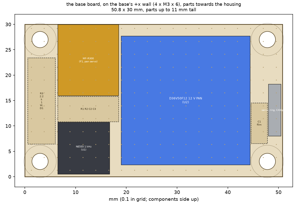 |
D36V50F12 (12 V PAN), the NE555 on the pendant loop's 12 V with its R1, R2, C1-C3, D1 and R3 (the 1 kHz pulses), MF-R300 (pan servo), the pan servo's 3-pin, the ring plug's tails, CAN through; D8 and F4 in the harness beside it |
| Bay level 0, 52 x 50 | 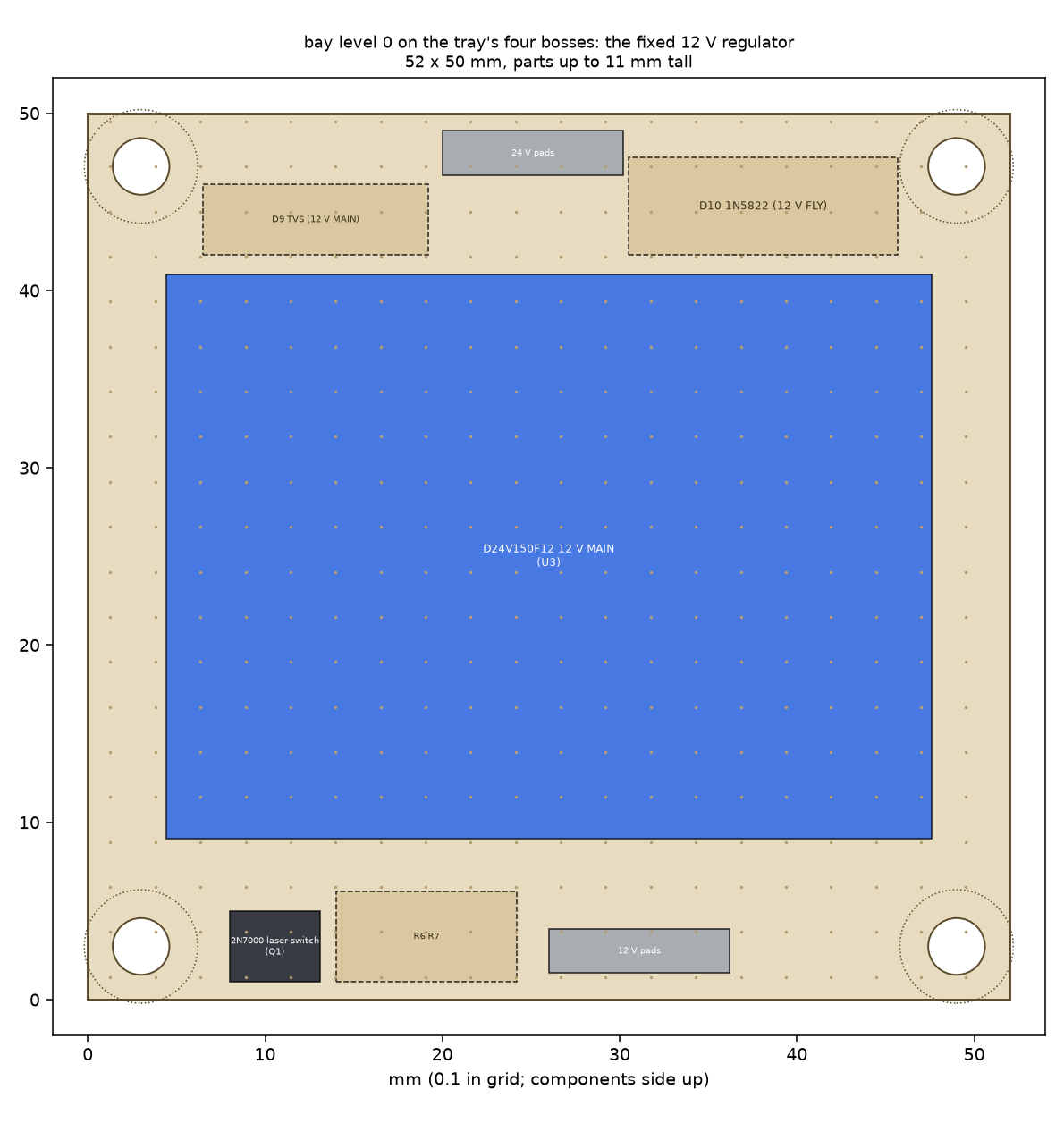 |
D24V150F12 (12 V MAIN, always on), the 2N7000 laser switch with R6, R7, the 2815's TVS (D9) and Schottky (D10), the 12 V and 24 V pads |
| Bay level 1, 52 x 50, on 12 mm standoffs | 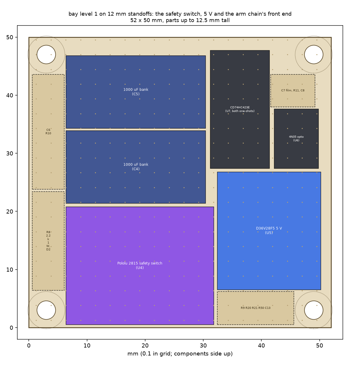 |
Pololu 2815 (slide switch OFF, glued), D36V28F5 (5 V), 2 x 1000 uF, the 4N35 with R8, D2, R9 and R50, the CD74HC423E (both one-shots, on 3.3 V) with R10, R11, C6-C8, the BUS_V divider |
| Bay level 2, 52 x 50, on 14 mm standoffs | 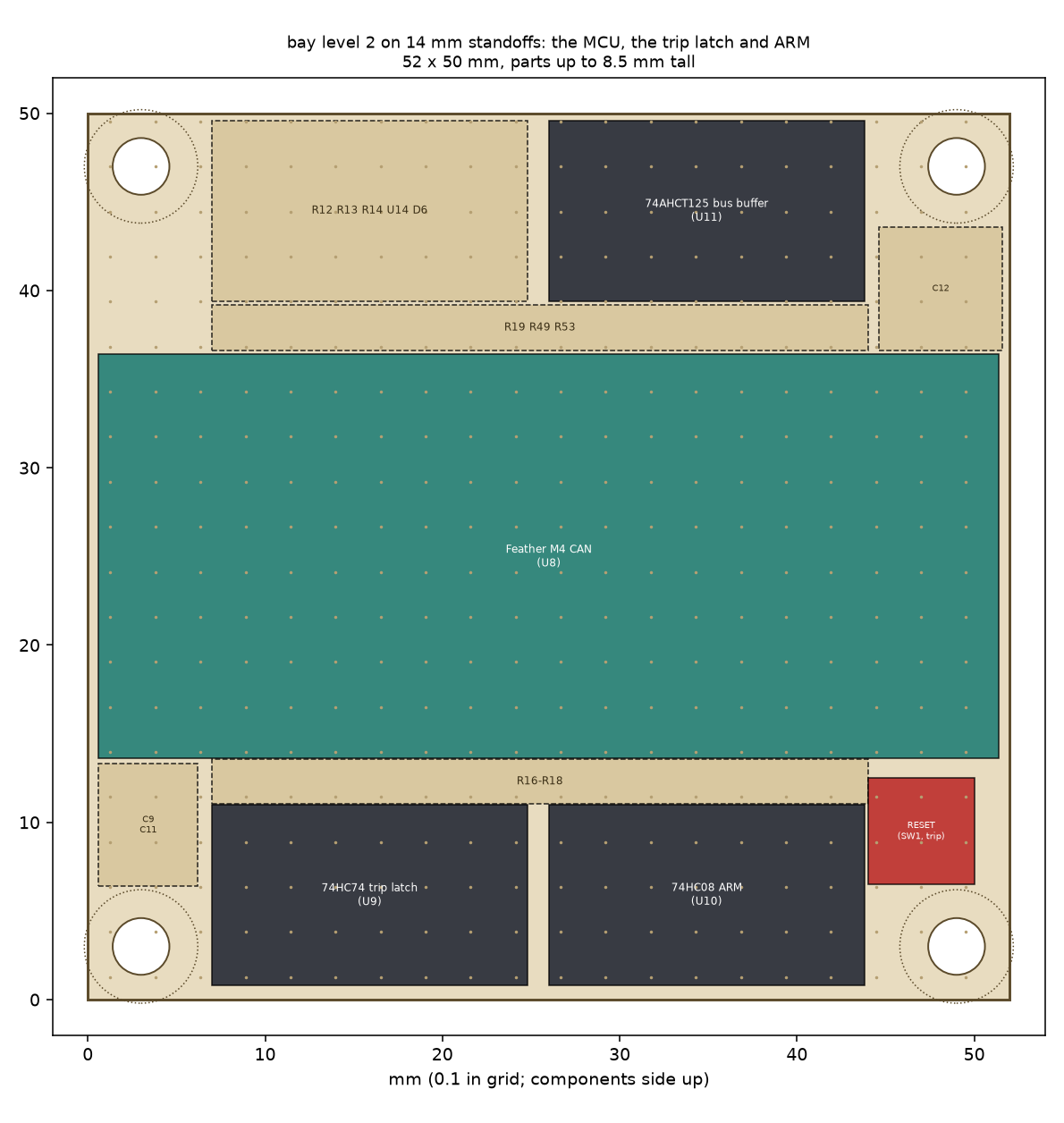 |
Feather M4 CAN, 74HC74 (the set-only trip latch) and 74HC08 (ARM, the trip's clock) on 3.3 V, the MCP120 power-up reset, 74AHCT125 (servo bus, laser gate) on 5 V, the recessed RESET, the pull-ups, R53 and the RX diode |
| Cartridge board, 50 x 44, on four posts over the cage | 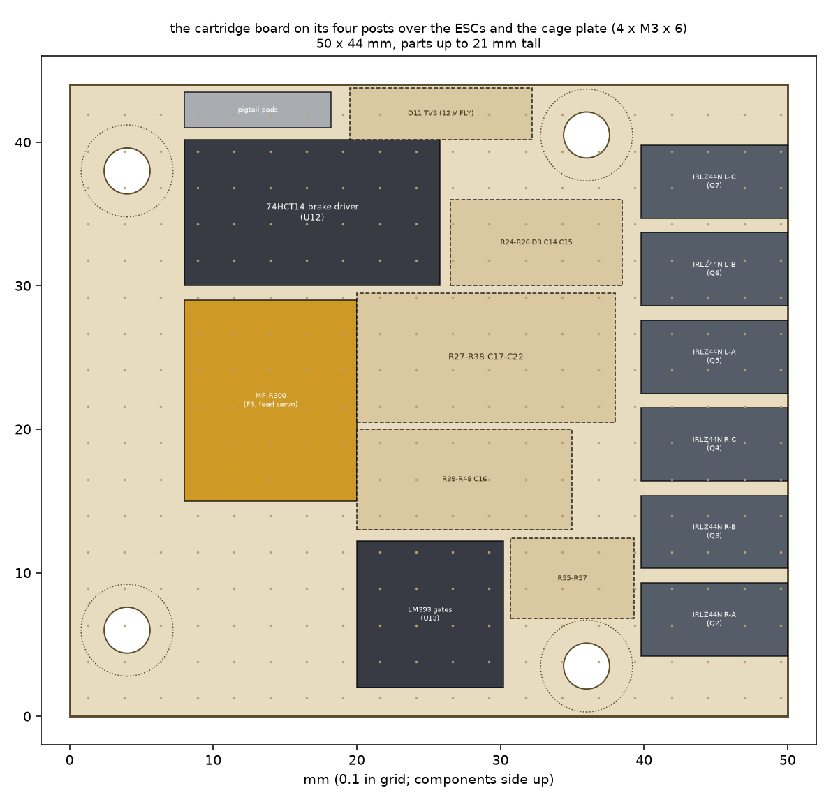 |
6 x IRLZ44N in a row along the front edge (phases to GND, 100 nF and 100 k at each gate), the 74HCT14 brake driver (three inverters, two gates each) and its RC, LM393 (gates), MF-R300 (feed servo), D11 (TVS), R55-R57 in the ESC and feed signals, the gates' resistors, the pigtail's pads; the two ESCs lie on the cage plate under it |
| Stand terminal board, 70 x 50 | 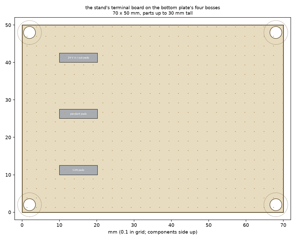 |
the 24 V, pendant and CAN junctions to the DT06 plug |
The perfboard is SparkFun's PRT-08619 (80 x 100 mm, plated through; one board cuts into two 52 x 50 pieces). Drill the corner holes to Ø3.2 at the standoff pattern (46 x 44 on the bay's boards). The Feather goes in on its two header rows, USB towards the bay's open face; nothing on level 2 stands taller than 8.5 mm.
7. Building the electrics, in order
- The stand's harness (C1, C1b) and the DT06 plug; continuity and polarity at the plug before the turret is fitted.
- The base: the DT04 with C2 and the in-line fuse; the base board; the ring's stator plug. With the turret off the stand, bench test 3.1 on the base alone: 12 V PAN present, the 555 at 1 kHz only while the pendant is held.
- The bay: level 0, then 1, then 2, each tested before the next goes on (the regulators' outputs with no load; then the 2815's ON from a lamp with its slide switch OFF; then glue the slide switch in OFF).
- The ring's rotor plug, the hall, the tilt servo and the laser; then the CT receptacles on the cradle.
- The cartridge board and its pigtail, on the bench with the cartridge off the turret: the brake FETs to the phase leads, the gates, the feed servo.
- Then docs/turret-bench-tests.md section 3 (the electrics without motors): the pulse train's fault list, the trip window, the brake timing with a lamp.
Rules for every session: the CT plugs go in and out only with the rocker off; the Feather is programmed over its USB-C port with the turret powered or not (D7 keeps the laptop and the turret's 5 V apart); the release check (12 V FLY off when the pendant is let go) opens the session.